I Can:
1. Sketch and model an auxiliary view of a given object. --
2. Describe the purpose and demonstrate the application of section lines and cutting plane lines in a section view drawing.
3. Sketch a full and half section view of a given object to communicate its interior features.
4. Apply assembly constraints to individual CAD models to create mechanical systems.
5. Explain how assembly constraints are used to systematically remove the degrees of freedom for a set of components in a given assembly.
The following pictures and explanations with tell you how I did and can, do these posted above.
Drawing Sheets:
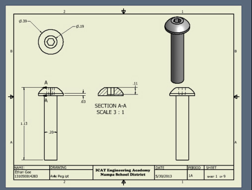
This is the axle peg. Dimensions explain the part and what was done to create it. The section tool was a great help in explaining the inside dimensions.
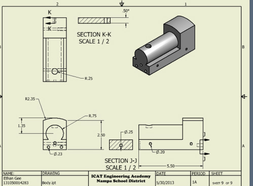
The body is the main part. This is what all of the parts go to. I sketched a circle, drew the body on the circle, and extruded it. Each of the holes had to have dimensions to be able to have all of the parts fit together. The hole on the top is where the stock goes. I put a plain on the edge of the circle, parallel to the bottom and used the hole tool.
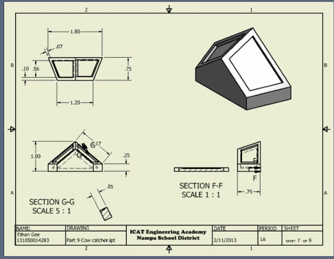
This is the cow catcher. I used the loft tool to create this part.The section tool is used help explain inside parts and not seen well parts better. Different views are here to show you the part completely.
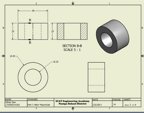
This was a pretty easy part to make. This is the hitch magnet. Two circles were drawn, and extruded.
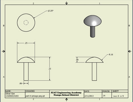
The linkage peg was a some what of a tricky part to create. I had to create a sketch at first, insert a circle, draw a T, liking it to the circle, cut the over needed lines, revolve that, and then extrude. The dimensions some what help explain how it was done. The part has dimensions to show what I did to create it.
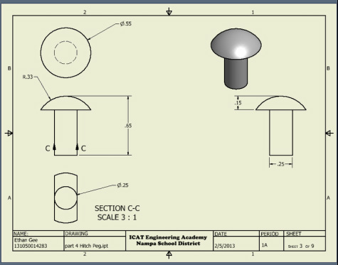
The hitch peg was made the same way that the linkage peg was. Dimensions again help explain the part.
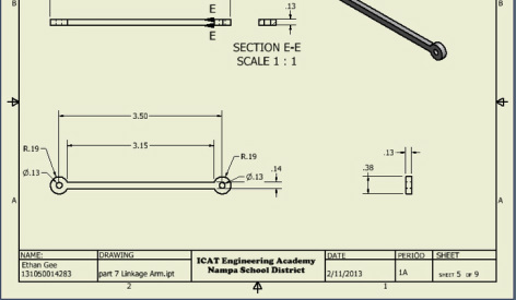
This is the linkage peg. This is what helps turn the wheels. This part was made by sketching a rectangle, putting two exact circles at the end, trim unneeded lines, and then extrude.
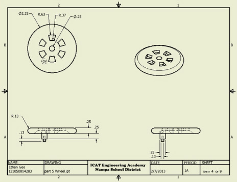
This is the wheel. There were four of them of course and only one was given dimensions because they are all the same, obviously. The dimensions show what was needed to make this part. To make the holes in the wheel, I had to make a circle and just extrude them. For the mid, almost triangular looking holes I had to draw lines off of the mid circle, cut the unneeded lines from the sketch, then simply extrude.
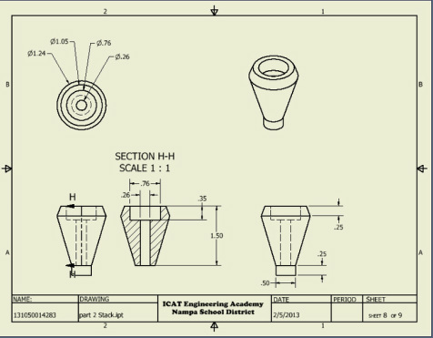
This is the stack to the train. The dimensions explain how the part can be and was created. I used the section tool to show inside dimensions and give a more explaining view of the inside. This part was mainly made by making a section and then revolving it. The dimensions completed it.

This is the exploded view of the toy train. I created an exploded view in Audodesk and put it in an ICAT drawing sheet. There are bubble labels and a graph with numbers to match with the bubbled numbers. These tell what the parts are.
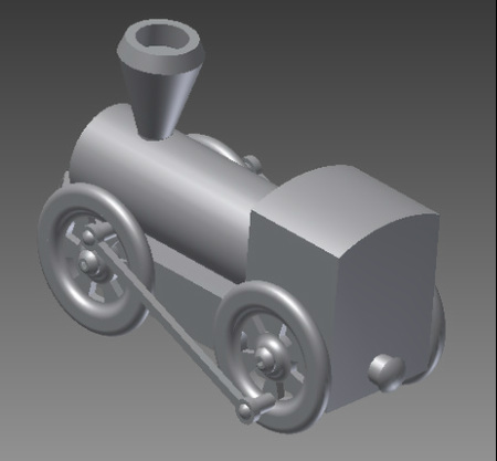
All of the parts were assembled together. This was the final Assembly!
